## Sửa Tivi Onix Crystal 40: Cuộc Chiến Vô Vọng!
Một buổi sáng đẹp trời, tôi nhận được cuộc gọi bất ngờ từ một người lạ tự giới thiệu là kỹ thuật viên, đang gặp khó khăn với chiếc tivi Onix Crystal 40 bị chết nguồn do chập mạch ở khu vực 3.3V. Anh ta làm việc ở nước ngoài và đang về nghỉ phép ngắn ngày, muốn sửa chữa khẩn cấp.
Tò mò, tôi đồng ý cho anh ta đến. Thay vì mang mạch, anh ta mang cả chiếc tivi đến. Tôi mở nắp sau và kiểm tra theo hướng anh ta đã thử sửa chữa: nguồn vào 3.3V của một IC bị đoản mạch. Mạch này tích hợp nguồn và bộ xử lý.
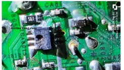
Hình ảnh IC (không đủ rõ để đọc số hiệu) và MOSFET cấp nguồn cho nó được thể hiện bên dưới:
Vùng đầu vào bị đoản mạch. Mặc dù anh ta đã dành nhiều giờ để tìm vị trí đoản mạch nhưng không thành công do thiếu sơ đồ mạch và thời gian eo hẹp vì lịch trình nghỉ phép bận rộn. Tôi cắt đường cấp nguồn vào IC và kiểm tra, phát hiện chính đường cấp nguồn bị đoản mạch. Tiếp tục kiểm tra MOSFET, cũng bị đoản mạch. Vậy là vùng 5V bị đoản mạch! Tôi sử dụng đồng hồ vạn năng analog (dải X1), rất hữu ích trong loại sửa chữa này. Ta có thể kiểm tra diode, transistor, MOSFET và cả tụ điện bằng đồng hồ vạn năng analog.
Jestine Yong luôn đề xuất sử dụng loại đồng hồ này trong sách hướng dẫn sửa chữa của ông ấy. Tôi bảo anh ta để lại tivi cho tôi để tìm lỗi kỹ hơn và tập trung vào công việc trong thời gian nghỉ phép ngắn ngủi.
Tôi tháo tụ điện liền kề và truy vết đường dây 5V. Tôi tháo cả ba tụ điện lớn còn lại để truy vết. Sau nhiều giờ, tôi phát hiện đường dây tách làm đôi. Tôi cắt đường dây dẫn vào khu vực IC chính. Vẫn bị đoản mạch. Tôi truy vết đường dây còn lại, dẫn đến phía sau jack USB. Có một điện trở 0 Ohm trên đường dây, tôi tháo nó ra và đoản mạch ở vùng MOSFET biến mất, nhưng vẫn còn ở đầu kia. Có một tụ điện rất nhỏ ở phía bên kia, là tụ lọc xuống đất. Do trực giác, tôi tháo nó ra. Cuối cùng, đoản mạch biến mất!
Tụ điện nhỏ bật ra khỏi nhíp và rơi mất. Nhưng không sao, vì nó có thể là tụ lọc giá trị thấp. Mũi tên vàng trong hình dưới đây chỉ vị trí của tụ điện “lang thang” này!
Tôi hàn lại các đường dây đã cắt và cấp nguồn. Đầu ra nhấp nháy, cho thấy có vấn đề ở khu vực nguồn chính hoặc có thêm tụ điện hoặc linh kiện bị rò rỉ. Khi anh ta quay lại theo lời hẹn, tôi cho anh ta xem và nói rằng tôi sẽ tiếp tục truy vết lỗi và anh ta có thể tiếp tục lịch trình bận rộn. Tôi thay thế tụ 10uF/50V ở khu vực nguồn chính vì đó là linh kiện quan trọng có thể gây ra sự cố. Tôi tháo và kiểm tra tụ điện lọc xung ở khu vực nguồn chính.
Nó hoạt động tốt. Dưới đây là hình ảnh khu vực chuyển mạch cùng với bản phác thảo tôi vẽ để tìm lỗi:
Tôi kiểm tra từng linh kiện ở khu vực nguồn chính và mọi thứ đều ổn. Điện áp vào IC chuyển mạch UB101 cũng có, điều này hiển nhiên vì nguồn đã được bật. Tôi chuyển sự chú ý sang phía thứ cấp và kiểm tra toàn bộ khu vực xem có linh kiện nào bị rò rỉ hay đoản mạch không, nhưng không tìm thấy. Trong quá trình này, tôi cũng vẽ bản phác thảo khu vực IC TL431:
Tôi liên tục báo cáo tiến độ cho khách hàng và xin phép thực hiện một bài kiểm tra “sinh tử” trên mạch. Vấn đề khó khăn nhất là nguồn được tích hợp. Nếu nguồn riêng biệt, ta có thể dễ dàng tìm ra vấn đề mà không làm hỏng mạch chủ. Tôi muốn sử dụng mô-đun bốn dây (mô-đun 5-24V mà tôi đã đề cập trong nhiều bài viết trước – xem: [link bài viết]) và kiểm tra xem phía thứ cấp có hoạt động không, và kết nối nó. Ưu điểm của bài kiểm tra này là nếu có linh kiện hoặc khu vực nào bị rò rỉ hoặc đoản mạch khi bật nguồn, nó sẽ bị cháy và ta có thể dễ dàng tìm thấy. Đó là lý do tại sao tôi gọi đây là bài kiểm tra “sinh tử”. Tôi tháo IC chuyển mạch SMD và MOSFET khỏi khu vực nguồn chính và kết nối mạch nguồn ngoài. Dưới đây là hình ảnh mạch, với phần điều khiển nguồn chính được thay thế bằng mạch ngoài:
Optocoupler SMD 817 đã được thay thế bằng một cái mới để đảm bảo không có lỗi trong phản hồi. Chân 3 & 4 của opto ở cả hai mạch được nhấc lên. Sau đó, chân 3 & 4 của opto trên mạch combo được nối với mạch ngoài, nơi chân 3 & 4 của nó được nối. Một loại kết nối bypass để đảm bảo rằng điện áp cho mạch combo được tạo ra và điều khiển như thiết kế. Tôi đã làm điều này nhiều lần trước đây và đã báo cáo trong các bài viết trước đây và tôi không lặp lại chi tiết đầy đủ một lần nữa. Khi tôi bật nguồn, đèn báo serial sáng, cho thấy có đoản mạch ở đâu đó. IC âm thanh (RDA3118E28) bị cháy trong tích tắc, cho thấy đó là thủ phạm. Một tụ 470uF/16V cũng bị phồng nhẹ, tôi đã thay thế sau đó.
Mặc dù tôi đã tháo IC, tôi vẫn cảm thấy có vấn đề ở mạch khác. Mặc dù tôi đã kiểm tra toàn bộ mạch bằng đồng hồ vạn năng analog, nhưng tôi không tìm thấy đoản mạch trực tiếp nào. Tôi tháo mạch nguồn ngoài và kết nối mô-đun ba dây (một lần nữa đã được đề cập trong nhiều bài viết trước đây và do đó không lặp lại việc sử dụng của nó – xem: [link bài viết]).
Nhưng không có đầu ra khi bật nguồn, cho thấy mạch có lỗi ở những nơi khác. Tôi tháo mô-đun và lắp lại các linh kiện đã tháo và cấp nguồn để xem liệu có sự hồi sinh kỳ diệu nào xảy ra không. Nhưng không có gì xảy ra ngoại trừ một vài cú sốc điện tôi nhận được từ tụ điện nguồn vì tôi quên xả tụ trước khi làm việc ở khu vực nguồn chính!
Khách hàng yêu cầu dừng việc điều tra thêm và tôi lắp lại mạch như cũ và đóng nắp sau để khách hàng lấy đi vào ngày hôm sau. Vì anh ta cũng là kỹ thuật viên, anh ta dự định thay thế mạch bằng mạch Android thông minh mới nhất và nâng cấp nó.
Vì vậy, nhiều giờ lao động và thức khuya của tôi đã dẫn đến kết quả thất bại! Tuy nhiên, tôi có được sự thỏa mãn? Đó là dành cho các bạn đọc quyết định! (LOL)
Bài viết này được thực hiện bởi Parasuraman Subramanian từ Ấn Độ. Ông 74 tuổi và có hơn 30 năm kinh nghiệm xử lý thiết bị cổ điển như radio đèn, amply, máy ghi âm băng cuộn và hiện đang theo học các lớp công nghệ mới do Hiệp hội Kỹ thuật viên Điện tử bang Kerala tổ chức. Ông tốt nghiệp BBA, có bằng kỹ sư vô tuyến và đã nghỉ hưu với chức vụ Giám đốc điều hành của một công ty Mỹ. Hiện ông đang làm tư vấn cho bệnh viện và các tổ chức khác.
#SửaChữaTivi #OnixCrystal40 #ChậpMạch #LỗiNguồn #ĐiệnTử #KỹThuậtSửaChữa #ThấtBại #CâuChuyệnSửaChữa #ThủThuậtĐiệnTử #KinhNghiệmSửaChữa
Hãy viết bài báo dài đầy đủ chuyên nghiệp hay bằng tiếng VIệt kèm hashtag Futile Attempt To Revive Onix LED TV Model Crystal 40

One fine morning I had a surprise call from an unknown person introducing himself quoting a few references stating that he was a technician of different field and he could not resolve a problem of shorting he found out in the 3.3V input area because of which the TV was dead. He worked abroad and was on leave for a few days and wanted to fix it urgently.
Well, my curiosity got aroused and I gave him green signal to come over. As I suggested bringing the TV instead of the board, he brought it. I opened the back cover of the TV and followed what the troubleshooting was done by him. The 3.3 V input to an IC was dead short. Let us have a look at the board which combined power supply and processor together.
The IC for which the 3.3V input has to come is shown below (unfortunately the picture is not clear enough to read the number) and the Mosfet that supplies the voltage is shown on its side:
The input area was dead short. Even though this gentleman spent several hours trying to locate the short, he was not able to find it out because of the absence of a schematic diagram and mostly because of lack of time as his leave period was packed with social visits and other engagements. Anyhow, I cut the input to the IC and checked and found out that the input itself was shorting. Then I checked the input of the Mosfet and that was also short. So, the 5V area itself was short! I used analogue multimeter (X1 range) which is the best to use for such troubleshooting. We can check diodes, transistors and Mosfets using the Analogue Multimeter and can even check for any short or leak of fixed capacitors too.
Jestine Yong always suggests use of this Multimeter in his repair books. I told him to leave the TV with me for extensive tracking and requested him to attend to his essential activities during the short period of his leave.
I removed the adjacent capacitor and tracked where the rail of the 5V was going to. I removed all the three remaining large capacitors also in order to track. After spending several hours of tracking, I located that the track was split into two. I cut the track that was going towards inside of the main IC area. The short remained. Then tracked the other line and traced it reaching behind the USB socket. There was a zero ohm resistor in the track and I removed it and found that the short in the Mosfet area was removed, but remained at the other end. There was a very tiny capacitor at the other side which was a filter capacitor to the ground. On a sheer intuition, I just removed it. The short had gone at-last!
The tiny capacitor jumped out of the tweezer and fell somewhere and I lost it. Anyhow that did not matter as it could be a low value filter. The yellow arrow in the following picture would show you where the ‘vagabond’ capacitor was!
Then restored the rest of the cut tracks and applied power. The output was pulsating indicating that either there was a problem in the primary area or there are some more leaky caps or components on the board. As he had come home for a follow-up visit as per my call, I showed this to him and told him that I would try tracing the culprits in the board and let him proceed with his tight schedules. I replaced the 10uF/50V capacitor in the primary as that was a key component that could cause problems. Then removed and checked the fixed capacitor that filters the switching in the primary area.
It was found ok. Following is the Switching area picture along with a rough sketch I drew to track problems in the area:
I checked each and every component in the primary area and everything was ok. The voltage to UB101 switching IC was also present, which anyhow was obvious as the PS was getting on. Then I turned my attention to the secondary side and combed the entire area for any leaky or shorted components and could not find any. In the process I drew a sketch of the TL431 IC area as well:
I kept reporting the progress to the customer and took his clearance to do a do or die test in the board. The most difficult problem was that the PS was combined. If PS was separate, we could have easily found out the problem without causing damages to the mother board. Here we stand a chance and precisely that is what happened. I wanted to use a four wire module (5-24 board about which I have already covered in many previous articles – Just see:
) and check whether the secondary was working and connected it. The advantage of such a test was that if any of the components or areas are having leak or short on switch on, that will fume and we can easily locate it. That is why we call it the do or die test. I removed the SMD switching IC and Mosfet from the primary and connected the external PS board. Following is the picture of the board, primary control of which is taken over by the separate board:
The SMD optocoupler 817 was replaced beforehand with a new one for ensuring that there was no mistake in the feedback. The pins of 3 & 4 of the opto in both the boards were lifted up Then the pins 3 & 4 of opto in the combo board was connected to the external board where its 3 & 4 was connected. A type of bypass connection so as to ensure that the voltages for the combo board were generated and controlled as how it was designed for. I have done this many times before and reported in my articles before and I am not repeating it in full details again. Then when I powered it up, the serial bulb lit indicating that there was some short somewhere. The audio IC (RDA3118E28) fumed within microseconds indicating that that was the culprit. One 470uF/16V also bulged a bit, which I replaced later.
Though I removed the IC, I was feeling that there were problems in the board elsewhere too. Though I combed the entire board using the analogue multimeter, I could not find any direct short. I removed the external PS board and connected a three wire module (once again already covered by me in many previous articles and hence not repeating its use – Just see: )
But no output came on switch on, indicating that the board had failures elsewhere also. I removed the module and put back the removed components and applied power to see whether some miraculous revival would happen. But nothing happened except a couple of shocks that I got from the tank capacitor as I forgot to discharge it before working on the primary area!
Further investigation was abandoned as advised by the customer and the board was put back like before and back cover closed for pick up by the customer, which he did the next day. As he was a technician, he was planning to replace the board with the latest android smart board and upgrade it.
So, several hours of my toil and burnt night oil resulted in utter fiasco! Nevertheless, can I have satisfaction collected to the bag? It is for you readers, to decide and it is awaiting your nod to enter! (LOL)
This article was prepared for you by Parasuraman Subramanian from India. He is 74 years old and has more than 30 years’ experience in handling antique equipment like Valve Radio, Amps, Reel Tape Recorders and currently studying latest tech-classes conducted by Kerala State Electronics Technicians’ Association. He has done graduation in BBA degree, private diploma in Radio Engineering and retired as MD of a USA company. Presently working as Consultant to Hospital and other institutions.
Please give a support by clicking on the social buttons below. Your feedback on the post is welcome. Please leave it in the comments.
P.S-If you enjoyed reading this, to subscribe to my blog (free subscription). That way, you’ll never miss a post. You can also forward this website link to your friends and colleagues-thanks!
You may check on his previous article on
Likes (1)Dislikes
 (0)
(0)
//
(tiêu đề viết lên đầu)
Futile Attempt To Revive Onix LED TV Model Crystal 40
One fine morning I had a surprise call from an unknown person introducing himself quoting a few references stating that he was a technician of different field and he could not resolve a problem of shorting he found out in the 3.3V input area because of which the TV was dead. He worked abroad and was on leave for a few days and wanted to fix it urgently.
Well, my curiosity got aroused and I gave him green signal to come over. As I suggested bringing the TV instead of the board, he brought it. I opened the back cover of the TV and followed what the troubleshooting was done by him. The 3.3 V input to an IC was dead short. Let us have a look at the board which combined power supply and processor together.
The IC for which the 3.3V input has to come is shown below (unfortunately the picture is not clear enough to read the number) and the Mosfet that supplies the voltage is shown on its side:
The input area was dead short. Even though this gentleman spent several hours trying to locate the short, he was not able to find it out because of the absence of a schematic diagram and mostly because of lack of time as his leave period was packed with social visits and other engagements. Anyhow, I cut the input to the IC and checked and found out that the input itself was shorting. Then I checked the input of the Mosfet and that was also short. So, the 5V area itself was short! I used analogue multimeter (X1 range) which is the best to use for such troubleshooting. We can check diodes, transistors and Mosfets using the Analogue Multimeter and can even check for any short or leak of fixed capacitors too.
Jestine Yong always suggests use of this Multimeter in his repair books. I told him to leave the TV with me for extensive tracking and requested him to attend to his essential activities during the short period of his leave.
I removed the adjacent capacitor and tracked where the rail of the 5V was going to. I removed all the three remaining large capacitors also in order to track. After spending several hours of tracking, I located that the track was split into two. I cut the track that was going towards inside of the main IC area. The short remained. Then tracked the other line and traced it reaching behind the USB socket. There was a zero ohm resistor in the track and I removed it and found that the short in the Mosfet area was removed, but remained at the other end. There was a very tiny capacitor at the other side which was a filter capacitor to the ground. On a sheer intuition, I just removed it. The short had gone at-last!
The tiny capacitor jumped out of the tweezer and fell somewhere and I lost it. Anyhow that did not matter as it could be a low value filter. The yellow arrow in the following picture would show you where the ‘vagabond’ capacitor was!
Then restored the rest of the cut tracks and applied power. The output was pulsating indicating that either there was a problem in the primary area or there are some more leaky caps or components on the board. As he had come home for a follow-up visit as per my call, I showed this to him and told him that I would try tracing the culprits in the board and let him proceed with his tight schedules. I replaced the 10uF/50V capacitor in the primary as that was a key component that could cause problems. Then removed and checked the fixed capacitor that filters the switching in the primary area.
It was found ok. Following is the Switching area picture along with a rough sketch I drew to track problems in the area:
I checked each and every component in the primary area and everything was ok. The voltage to UB101 switching IC was also present, which anyhow was obvious as the PS was getting on. Then I turned my attention to the secondary side and combed the entire area for any leaky or shorted components and could not find any. In the process I drew a sketch of the TL431 IC area as well:
I kept reporting the progress to the customer and took his clearance to do a do or die test in the board. The most difficult problem was that the PS was combined. If PS was separate, we could have easily found out the problem without causing damages to the mother board. Here we stand a chance and precisely that is what happened. I wanted to use a four wire module (5-24 board about which I have already covered in many previous articles – Just see:
) and check whether the secondary was working and connected it. The advantage of such a test was that if any of the components or areas are having leak or short on switch on, that will fume and we can easily locate it. That is why we call it the do or die test. I removed the SMD switching IC and Mosfet from the primary and connected the external PS board. Following is the picture of the board, primary control of which is taken over by the separate board:
The SMD optocoupler 817 was replaced beforehand with a new one for ensuring that there was no mistake in the feedback. The pins of 3 & 4 of the opto in both the boards were lifted up Then the pins 3 & 4 of opto in the combo board was connected to the external board where its 3 & 4 was connected. A type of bypass connection so as to ensure that the voltages for the combo board were generated and controlled as how it was designed for. I have done this many times before and reported in my articles before and I am not repeating it in full details again. Then when I powered it up, the serial bulb lit indicating that there was some short somewhere. The audio IC (RDA3118E28) fumed within microseconds indicating that that was the culprit. One 470uF/16V also bulged a bit, which I replaced later.
Though I removed the IC, I was feeling that there were problems in the board elsewhere too. Though I combed the entire board using the analogue multimeter, I could not find any direct short. I removed the external PS board and connected a three wire module (once again already covered by me in many previous articles and hence not repeating its use – Just see: )
But no output came on switch on, indicating that the board had failures elsewhere also. I removed the module and put back the removed components and applied power to see whether some miraculous revival would happen. But nothing happened except a couple of shocks that I got from the tank capacitor as I forgot to discharge it before working on the primary area!
Further investigation was abandoned as advised by the customer and the board was put back like before and back cover closed for pick up by the customer, which he did the next day. As he was a technician, he was planning to replace the board with the latest android smart board and upgrade it.
So, several hours of my toil and burnt night oil resulted in utter fiasco! Nevertheless, can I have satisfaction collected to the bag? It is for you readers, to decide and it is awaiting your nod to enter! (LOL)
This article was prepared for you by Parasuraman Subramanian from India. He is 74 years old and has more than 30 years’ experience in handling antique equipment like Valve Radio, Amps, Reel Tape Recorders and currently studying latest tech-classes conducted by Kerala State Electronics Technicians’ Association. He has done graduation in BBA degree, private diploma in Radio Engineering and retired as MD of a USA company. Presently working as Consultant to Hospital and other institutions.
Please give a support by clicking on the social buttons below. Your feedback on the post is welcome. Please leave it in the comments.
P.S-If you enjoyed reading this, to subscribe to my blog (free subscription). That way, you’ll never miss a post. You can also forward this website link to your friends and colleagues-thanks!
You may check on his previous article on
Likes(1)Dislikes(0)
//
[su_box title=”Liên hệ đặt mua sản phẩm tại bài viết tại Viễn Đông Mobile” style=”default” box_color=”#3be863″ title_color=”#FFFFFF” radius=”3″]
Viễn Đông Mobile là cửa hàng chuyên kinh doanh các sản phẩm điện tử phục vụ nhu cầu chơi game, bao gồm:
- Gaming phone: Điện thoại cấu hình mạnh, tối ưu cho việc chơi game.
- Máy tính bảng chuyên gaming: Màn hình lớn, hiệu năng cao, trải nghiệm game tốt hơn.
- Phụ kiện cao cấp: Tai nghe, bàn phím, chuột,… hỗ trợ game thủ.
Thông tin liên hệ:
- Địa chỉ: 211 đường 3/2, phường 11, quận 10, TP.HCM
- Điện thoại: 0777600020
- Email: contact@viendongmobile.com

Bản đồ chỉ đường
[su_gmap address=”211 đường 3/2 phường 11 quận 10 Tp hồ chí minh Việt Nam” responsive=”yes”] xin chào Xem chi tiết và đăng ký[featured_image]