## Sửa Chữa Thành Công: Deck Cassette Sony TC-K333ESG Lỗi Tắt Mở Ngắt Quãng!
Đây là một trong ba chiếc máy được mang đến bởi một khách hàng mới từ nơi xa, nhờ lời giới thiệu của người quen! Khách hàng phản ánh máy hoạt động tốt trong vài phút rồi tắt ngắt quãng.
Sau khi kiểm tra, tôi xác nhận sự cố. Đầu tiên, tôi tải xuống bản hướng dẫn dịch vụ từ mạng để công việc dễ dàng hơn. Tôi mở chiếc Deck xinh xắn này ra, bên trong khá sạch sẽ, chỉ có một lớp bụi mịn bám trên các bo mạch. Theo kinh nghiệm, tôi bắt đầu kiểm tra từ bo mạch nguồn. Hãy cùng xem bên trong chiếc Deck được thiết kế tốt này, có thể quan sát được từ cả hai phía sau khi tháo nắp. Các bo mạch được lắp trong khung kim loại ở giữa.
Bo mạch ở giữa là bo mạch nguồn, được gắn với bo mạch chọn điện áp. Tôi tháo nó ra sau khi đánh dấu các đầu nối một cách cẩn thận và ngắt kết nối tất cả các đầu nối.
Màu sắc của dây dẫn được ghi rõ ràng trên PCB, giúp việc bảo trì rất dễ dàng, điều này tôi thực sự đánh giá cao. Ở một số vị trí, thậm chí còn ghi rõ số đầu nối cần kết nối! Tuyệt vời! Một thiết kế thân thiện với người sửa chữa!
Bộ máy này đã từng được sửa chữa trước đó, tôi thấy một vài tụ điện đã được thay thế và dấu vết của việc sửa chữa trước đây. Khách hàng xác nhận rằng một kỹ thuật viên khác đã cố gắng sửa chữa nhưng không thành công, điều này khiến công việc của tôi phức tạp hơn vì tôi cần phải tìm kiếm những thay đổi và sửa đổi trước đó!
Vì màn hình đếm nhấp nháy khi động cơ chạy và máy tắt trong những trường hợp đó, tôi nghi ngờ nguồn DC không ổn định hoặc có thứ gì đó đang tiêu thụ quá nhiều dòng điện khiến vi điều khiển tắt máy. Máy này không có đèn báo chế độ chờ; nhưng đèn bên trong Deck băng vẫn sáng và động cơ capstan vẫn chạy, nhưng tất cả các màn hình đều tắt. Tôi đã thay thế một tụ điện điện phân nhỏ trên bo mạch nguồn và làm sạch lại cả hai bo mạch, bôi trơn tất cả các đầu nối. Sau đó, tôi kết nối lại các bo mạch và cấp nguồn. Máy hoạt động và tôi không muốn load băng để phát ở giai đoạn này. Nhân tiện, việc mở và đóng cửa là tự động bằng cách nhấn nút, rõ ràng là điều khiển bằng động cơ. Tôi để máy chạy và đi vào bếp ăn sáng. Khi quay lại, máy đã tắt, xác nhận rằng có vấn đề gì đó ở bo mạch IC chính. Tôi thấy một vài tụ điện điện phân cũng đã được thay thế trên bo mạch đó. Hai transistor điều khiển điện áp và hai IC chỉnh lưu không bị nóng, cho thấy không có hiện tượng rò rỉ dòng điện. Khả năng tiếp theo là lọc DC không đúng cách, làm mất ổn định hệ thống IC. Vì bo mạch được phủ một lớp vecni tốt nên tôi không nhìn thấy bất kỳ mối hàn khô nào. Kỹ thuật viên trước đó đã làm sạch lại tất cả các điểm cần thiết. Vì vậy, tôi đã thay thế tất cả các tụ điện điện phân còn lại trên bo mạch đó, bao gồm cả 10uF, 47uF, 100uF, v.v. Sau đó, tôi tháo ra và bôi trơn tất cả các đầu nối, sau đó hệ thống hoạt động khi được cấp nguồn và duy trì ổn định.
Nhưng hiện tượng nhấp nháy trên màn hình đếm vẫn còn. Tôi load một băng và phát liên tục bằng cách đổi mặt A và B để kiểm tra xem vấn đề đã được giải quyết chưa. Sau khi đảm bảo mọi thứ ổn, tôi tháo bo mạch hiển thị và kiểm tra. Nó đã được sửa chữa trước đó với các đường dẫn được nối bằng dây và một vài tụ điện điện phân đã bị tháo bỏ. Nhưng việc làm sạch lại toàn bộ bo mạch chưa được thực hiện. Tôi đã làm sạch lại toàn bộ bo mạch và kết nối nó từ bên ngoài để nghiên cứu xem còn lỗi gì khác trong mạch vì bộ đếm không hoạt động.
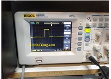
Sau đó, sử dụng Oscilloscope để nghiên cứu các dạng sóng và kết quả như sau:
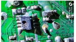
Kiểm tra cuối cùng là trên chân dao động của IC, cho thấy tín hiệu yếu và bị méo. Tôi đã nghiên cứu sơ đồ của IC này và các điện áp cần tìm ở mỗi chân. Hãy cùng xem:
Điện áp cung cấp và các điện áp đầu vào khác đều ổn. Nhưng điện áp đầu ra không chính xác. Tôi thậm chí đã thay thế tụ điện 333K trong phần dao động. Điện trở 10K cũng ổn. Hai tụ điện điện phân là mới (đã được kỹ thuật viên trước đó thay thế). Khi tôi thông báo cho khách hàng rằng IC bị nghi ngờ, mà việc tìm kiếm lại khó khăn, anh ấy cho biết máy đã như vậy khi anh ấy mua lại với giá máy cũ nhưng vẫn hoạt động và điều đó không thành vấn đề.
Vì vậy, tôi đã dừng lại và lắp lại bo mạch vào vị trí cũ. Tôi thấy một chút nhấp nháy trên các chữ số, cho thấy một số dữ liệu đã đến nhưng không đủ mạnh.
Sau đó, tôi chạy máy trong vài giờ và thấy nó hoạt động hoàn hảo, sau đó tôi lắp lại tấm đáy, nắp trên và các tấm gỗ bên. Nhiệm vụ hoàn thành với nhiều trải nghiệm đa dạng và do đó sự hài lòng thu được đã được ghi nhận vào bộ sưu tập mà không cần do dự!
Bài viết này được soạn bởi Parasuraman Subramanian từ Ấn Độ. Ông 74 tuổi và có hơn 30 năm kinh nghiệm xử lý thiết bị cổ điển như Radio Valve, Amps, Máy ghi âm băng cuộn và hiện đang theo học các lớp học công nghệ mới nhất do Hiệp hội Kỹ thuật viên Điện tử Tiểu bang Kerala tổ chức. Ông tốt nghiệp cử nhân Quản trị Kinh doanh (BBA), có bằng kỹ sư vô tuyến riêng và đã nghỉ hưu với chức danh Giám đốc điều hành (MD) của một công ty Mỹ. Hiện ông đang làm tư vấn cho bệnh viện và các tổ chức khác.
Vui lòng ủng hộ bằng cách nhấp vào các nút mạng xã hội bên dưới. Phản hồi của bạn về bài viết này rất được hoan nghênh. Vui lòng để lại bình luận của bạn.
Ghi chú: Nếu bạn thích đọc bài viết này, hãy nhấp vào đây để đăng ký blog của tôi (miễn phí). Bằng cách đó, bạn sẽ không bỏ lỡ bất kỳ bài đăng nào. Bạn cũng có thể chuyển tiếp liên kết trang web này cho bạn bè và đồng nghiệp của mình – cảm ơn!
Bạn có thể xem bài viết trước của ông ấy về chủ đề “Lưu Trữ Nguồn SMPS Máy Tính – Phần 14”
#SửaChữaDeckCassette #SonyTCK333ESG #LỗiTắtMở #NgắtQuãng #HưHỏngĐiệnTử #BảoTrìThiếtBịCổ #KinhNghiệmSửaChữa #ĐiệnTửCổ #MáyGhiÂmBăng #ChuyênGiaSửaChữa
Hãy viết bài báo dài đầy đủ chuyên nghiệp hay bằng tiếng VIệt kèm hashtag Intermittent On-Off Problem Solved In SONY Cassette Deck Model TC-K333ESG

This was one among the three sets brought by a new customer from a faraway place; a result of mouth-to-mouth publicity! The complaint reported was that it worked fine for a few minutes and then goes off and was intermittent.
Checked and found it to be true. First of all I downloaded its service manual from the net to make things easy. I opened this lovely Deck, which was almost clean inside except for settled fine dust on the boards. As per practice, the first investigation began from the power supply board. Let us have a look at the inside of this well designed deck which can be viewed from both sides after removing the covers. The boards are fit in a metal frame in the centre.
The board in the middle was the power supply board attached to the voltage selector board. I removed this after marking the connectors properly and disconnecting all connectors.
The colors of the wires were well written on the PCB making service very easy, which I really appreciated. In a few places it was written to which connector number that should go to! Vow! What a service-friendly design!
The set indeed had been serviced before and I saw a few capacitors replaced and traces of rework done. The customer confirmed that a futile attempt was made by another technician, which made my work more complicated as I need to then look for tampering and modifications!
As the counter display was flickering when the motor was running and the set got off on such occasions, I suspected that the DC supply was not proper or something was drawing excess current making the µController shut off. There was no indication of any standby in this set; but the lamp inside the tape deck remained lit up and the capstan motor running, but all displays shut off. I replaced a small electrolytic capacitor in the PS board and retouched both the boards, lubricated all connectors and made it pukka. Then reconnected the boards and applied power. The set got on and I did not want to load a cassette to play at this stage. By the way, the door opening and closing was automatic at the press of a button, obviously a motor control. I allowed the set to be in on condition and went to the kitchen to have my breakfast. The set was found in off condition when I returned, confirming that something was wrong in the main IC board side. I saw a few electrolytic capacitors replaced in that board too. The two voltage control transistors and two regulator ICs were not getting hot indicating that there was no current drain. The next possibility was improper filtering of DC which destabilizes the system IC. As the board was well laminated with varnish, I could not see any dry solder as such. The other technician had retouched all points that were necessary. So I replaced all the rest of the electrolytic capacitors on that board, which included the 10uF, 47uF, 100uF etc. Then removed and lubricated all the connectors, upon which the system got on when powered and remained stable.
But the flickering in the counter display was still there. I loaded a cassette and played it continuously by changing the A and B sides to check whether the problem was solved. After ensuring that it was ok, I removed the display board and checked it. It was already tampered with tracks joined by wire and a couple of electrolytic caps removed. But retouch of the entire board was not done. I retouched the entire board and connected it externally to study what else was wrong in the circuit as the counter was not working.
Then using the Oscilloscope studied the wave forms and following are the results:
The last check was on the oscillator pin of the IC, which showed weak and distorted. I studied the schematic of this IC and the voltages to be found at each pin. Let us have a look:
The supply voltage and other input voltages were ok. But the output voltages were not proper. I even replaced the 333K capacitor in the oscillator section. The resistor of 10 K was also ok. The two electrolytic caps were new (replaced by the earlier technician already) When I informed the customer that the IC was suspected, availability of which was in doubt, he informed me that the set was like that only when he bought it as a used but working set and it did not matter.
So, I aborted my attempts and refit the board back in its place. I saw a minute flickering in the digits which showed that some data was reaching but was not strong enough.
Then run the set for several hours and found it to be working in perfect condition, upon which I fixed the bottom plate, top cover and side wooden plates. Mission accomplished with a lot of variety experiences and therefore the derived satisfaction was admitted to the collection bag without any hesitation!
This article was prepared for you by Parasuraman Subramanian from India. He is 74 years old and has more than 30 years’ experience in handling antique equipment like Valve Radio, Amps, Reel Tape Recorders and currently studying latest tech-classes conducted by Kerala State Electronics Technicians’ Association. He has done graduation in BBA degree, private diploma in Radio Engineering and retired as MD of a USA company. Presently working as Consultant to Hospital and other institutions.
Please give a support by clicking on the social buttons below. Your feedback on the post is welcome. Please leave it in the comments.
P.S-If you enjoyed reading this, click here to subscribe to my blog (free subscription). That way, you’ll never miss a post. You can also forward this website link to your friends and colleagues-thanks!
You may check on his previous article on
Likes (1)Dislikes
 (0)
(0)
//
(tiêu đề viết lên đầu)
Intermittent On-Off Problem Solved In SONY Cassette Deck Model TC-K333ESG
This was one among the three sets brought by a new customer from a faraway place; a result of mouth-to-mouth publicity! The complaint reported was that it worked fine for a few minutes and then goes off and was intermittent.
Checked and found it to be true. First of all I downloaded its service manual from the net to make things easy. I opened this lovely Deck, which was almost clean inside except for settled fine dust on the boards. As per practice, the first investigation began from the power supply board. Let us have a look at the inside of this well designed deck which can be viewed from both sides after removing the covers. The boards are fit in a metal frame in the centre.
The board in the middle was the power supply board attached to the voltage selector board. I removed this after marking the connectors properly and disconnecting all connectors.
The colors of the wires were well written on the PCB making service very easy, which I really appreciated. In a few places it was written to which connector number that should go to! Vow! What a service-friendly design!
The set indeed had been serviced before and I saw a few capacitors replaced and traces of rework done. The customer confirmed that a futile attempt was made by another technician, which made my work more complicated as I need to then look for tampering and modifications!
As the counter display was flickering when the motor was running and the set got off on such occasions, I suspected that the DC supply was not proper or something was drawing excess current making the µController shut off. There was no indication of any standby in this set; but the lamp inside the tape deck remained lit up and the capstan motor running, but all displays shut off. I replaced a small electrolytic capacitor in the PS board and retouched both the boards, lubricated all connectors and made it pukka. Then reconnected the boards and applied power. The set got on and I did not want to load a cassette to play at this stage. By the way, the door opening and closing was automatic at the press of a button, obviously a motor control. I allowed the set to be in on condition and went to the kitchen to have my breakfast. The set was found in off condition when I returned, confirming that something was wrong in the main IC board side. I saw a few electrolytic capacitors replaced in that board too. The two voltage control transistors and two regulator ICs were not getting hot indicating that there was no current drain. The next possibility was improper filtering of DC which destabilizes the system IC. As the board was well laminated with varnish, I could not see any dry solder as such. The other technician had retouched all points that were necessary. So I replaced all the rest of the electrolytic capacitors on that board, which included the 10uF, 47uF, 100uF etc. Then removed and lubricated all the connectors, upon which the system got on when powered and remained stable.
But the flickering in the counter display was still there. I loaded a cassette and played it continuously by changing the A and B sides to check whether the problem was solved. After ensuring that it was ok, I removed the display board and checked it. It was already tampered with tracks joined by wire and a couple of electrolytic caps removed. But retouch of the entire board was not done. I retouched the entire board and connected it externally to study what else was wrong in the circuit as the counter was not working.
Then using the Oscilloscope studied the wave forms and following are the results:
The last check was on the oscillator pin of the IC, which showed weak and distorted. I studied the schematic of this IC and the voltages to be found at each pin. Let us have a look:
The supply voltage and other input voltages were ok. But the output voltages were not proper. I even replaced the 333K capacitor in the oscillator section. The resistor of 10 K was also ok. The two electrolytic caps were new (replaced by the earlier technician already) When I informed the customer that the IC was suspected, availability of which was in doubt, he informed me that the set was like that only when he bought it as a used but working set and it did not matter.
So, I aborted my attempts and refit the board back in its place. I saw a minute flickering in the digits which showed that some data was reaching but was not strong enough.
Then run the set for several hours and found it to be working in perfect condition, upon which I fixed the bottom plate, top cover and side wooden plates. Mission accomplished with a lot of variety experiences and therefore the derived satisfaction was admitted to the collection bag without any hesitation!
This article was prepared for you by Parasuraman Subramanian from India. He is 74 years old and has more than 30 years’ experience in handling antique equipment like Valve Radio, Amps, Reel Tape Recorders and currently studying latest tech-classes conducted by Kerala State Electronics Technicians’ Association. He has done graduation in BBA degree, private diploma in Radio Engineering and retired as MD of a USA company. Presently working as Consultant to Hospital and other institutions.
Please give a support by clicking on the social buttons below. Your feedback on the post is welcome. Please leave it in the comments.
P.S-If you enjoyed reading this, click here to subscribe to my blog (free subscription). That way, you’ll never miss a post. You can also forward this website link to your friends and colleagues-thanks!
You may check on his previous article on
Likes(1)Dislikes(0)
//
[su_box title=”Liên hệ đặt mua sản phẩm tại bài viết tại Viễn Đông Mobile” style=”default” box_color=”#3be863″ title_color=”#FFFFFF” radius=”3″]
Viễn Đông Mobile là cửa hàng chuyên kinh doanh các sản phẩm điện tử phục vụ nhu cầu chơi game, bao gồm:
- Gaming phone: Điện thoại cấu hình mạnh, tối ưu cho việc chơi game.
- Máy tính bảng chuyên gaming: Màn hình lớn, hiệu năng cao, trải nghiệm game tốt hơn.
- Phụ kiện cao cấp: Tai nghe, bàn phím, chuột,… hỗ trợ game thủ.
Thông tin liên hệ:
- Địa chỉ: 211 đường 3/2, phường 11, quận 10, TP.HCM
- Điện thoại: 0777600020
- Email: contact@viendongmobile.com

Bản đồ chỉ đường
[su_gmap address=”211 đường 3/2 phường 11 quận 10 Tp hồ chí minh Việt Nam” responsive=”yes”] xin chào Xem chi tiết và đăng kýXem chi tiết và đăng ký[featured_image]