## Sửa Chữa “Khổ” Chiếc Ampli Marantz PM75: Hành Trình 6 Tháng!
Bài viết gốc: [Link bài viết gốc]
Chiếc ampli Marantz PM75 này đã trở lại xưởng sửa chữa của tôi, lần này với những vấn đề hoàn toàn khác so với lần đầu tiên. Lần đầu tiên, tôi đã báo cáo về độ phức tạp và thiết kế thô sơ của nó, với vô số dây nhợ kết nối rối rắm. Lần này, chỉ có đèn báo nguồn sáng lên, các nút bấm không phản hồi. Lần sửa chữa đầu tiên diễn ra vào tháng 7 năm 2024, và lần thứ hai vào tháng 12 năm 2024.
Tôi đã kiểm tra điện áp và phát hiện chúng đều ổn định. Bước tiếp theo là kiểm tra xem vi điều khiển có nhận được điện áp hay không. Tôi in ra tất cả các trang liên quan cần thiết để khắc phục sự cố. Để tiếp cận được vi điều khiển, nằm phía sau bảng điều khiển mặt trước, tôi phải tháo rời phần mặt trước và ngắt kết nối hàng chục dây dẫn, hầu hết là các dây quấn! Thậm chí việc tháo các bo mạch khác như jack tai nghe, đèn báo nguồn, công tắc chọn loa, bảng điều khiển âm trầm/âm sắc, công tắc chọn nguồn và bảng điều khiển âm lượng cũng rất khó khăn do chúng được kết nối với nhau bằng những dây ngắn. Tôi thực sự đã phải vật lộn để tháo chúng ra mà không gây ra bất kỳ hư hỏng nào.
Sau khi tháo các bo mạch, tôi sốc khi thấy những sửa chữa thô sơ do một kỹ thuật viên trước đó thực hiện (như tôi đã báo cáo lần trước). Hai IC bị mất trên bảng điều khiển âm lượng và một rơle được gắn ở dưới đáy, chức năng của nó chỉ có người thực hiện mới biết. Cần gạt của công tắc nguồn bị gãy, may mắn thay tôi tìm thấy nó bên trong bảng điều khiển mặt trước. Phần còn lại của cần gạt bị tuột ra khi tôi đang tháo bảng. Tôi quyết định để lại việc này cho sau.
Bảng điều khiển âm lượng có 9 đầu nối. Tôi đã đánh dấu cẩn thận và chụp ảnh trước khi tháo chúng. Tôi bọc các bo mạch liền kề bằng giấy bóng khí và dùng dây cao su để tránh tiếp xúc ngẫu nhiên. Sau đó, tôi cấp nguồn để kiểm tra vi điều khiển dựa trên sơ đồ mạch.
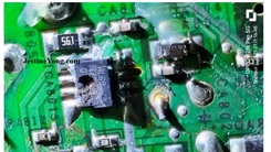
Tôi nhận thấy điện áp nguồn cấp cho IC bị thiếu. Tôi tìm thấy hai điện trở gần đó bị gỉ sét. Tôi đã thay thế hai điện trở 1kΩ và 330Ω, sau đó điện áp đã được cấp và vi điều khiển bắt đầu hoạt động. Các đèn LED mặc định cũng sáng lên như được đề cập trong sách hướng dẫn sử dụng.
Vì việc tiếp cận các bo mạch rất phức tạp, tôi quyết định thực hiện bảo trì phòng ngừa cho tất cả các bo mạch. Tôi đã tách riêng bo mạch vi điều khiển, thay thế tất cả tụ điện điện phân, công tắc vi mô và hàn lại các mối hàn khô. Tôi cũng hàn lại các mối hàn khô trên tất cả các bo mạch khác. Sau đó, tôi sửa chữa cần gạt công tắc nguồn. Tôi hàn lại chân gãy và cố định nó chắc chắn. Sau đó, tôi lắp lại bảng điều khiển mặt trước, lắp lại từng bộ phận của công tắc nút bấm. Cuối cùng, tôi đặt cần gạt vào rãnh của nó và nó được giữ chặt ở vị trí.
Sau đó, tôi lắp lại tất cả các bo mạch, buộc dây ở một vài chỗ để giữ chúng lại với nhau và làm cho nó trông tốt hơn. Tôi đã chạy thiết bị trong vài giờ trước khi lắp nắp trên và giao trả cho khách hàng.
Tổng chi phí sửa chữa (ước tính): [Cần thêm thông tin chi phí sửa chữa để điền vào phần này, ví dụ: 2.000.000 VND]
Về tác giả: Bài viết này được thực hiện bởi Parasuraman Subramanian từ Ấn Độ. Ông 74 tuổi, có hơn 30 năm kinh nghiệm sửa chữa thiết bị cổ như radio đèn, ampli, máy ghi âm cuộn băng và hiện đang theo học các lớp công nghệ mới nhất do Hiệp hội Kỹ thuật viên Điện tử Kerala tổ chức. Ông tốt nghiệp BBA, có bằng kỹ thuật Radio và đã nghỉ hưu với chức vụ Giám đốc điều hành của một công ty ở Mỹ. Hiện tại, ông làm tư vấn cho bệnh viện và các tổ chức khác.
#MarantzPM75 #SửaChữaAmpli #ĐiệnTửCổ #KỹThuậtSửaChữa #AmpliHư #BảoTrìThiếtBị #HànhTrìnhSửaChữa #ThửTháchSửaChữa #ĐiệnTử #CôngNghệCổ #KinhNghiệmSửaChữa
Hãy viết bài báo dài đầy đủ chuyên nghiệp hay bằng tiếng VIệt kèm hashtag Revisit Of MARANTZ PM75 Amplifier With Different Problems

I request you all to see this link, in which I had reported about the first visit of this complicated, crudely designed amplifier with a hell of a lot of interconnecting wires.
I am including only the images relevant to the problem handled. Though I had told the customer that without dismantling the entire set, cleaning all boards, replacing all electrolytic capacitors and retouching every point in the boards, this set would not work without any trouble for a prolonged time, budget as well as time from my side and my aversion in handling such crude sets prevented to carry out such mass repair works. Result was that it returned with the complaint that only power on indicator was working and there was no other response to keys pressed. The first visit was in July, 2024 and the second visit was in December, 2024. I did a primary check of all the voltages and found these to be present. Next step was to check whether the µController was getting the voltages. I took print out of all the relevant pages required for trouble shooting. In order for me to access the µController which was fixed under the front panel, I had to, not only detach the front portion, but also disconnect dozens of wires, most of which were wire-wound connections!
Without detaching the wires, the control board could not be removed from the panel as these were fixed with screws from behind. To get the panel, we also need to remove other boards such as headphone socket, power indicator, speaker selector switch, bass/tone control board, record selector switch and volume control board, all of which were inter connected with short wires. How these people assembled the set itself was a mystery! I really struggled to take it out without causing any man made damages and if I had cursed the designers, I cannot be blamed for that! Let us look at some step-by-step images:
After removing the boards, I was shocked to see the crude modifications done by a previous technician who had worked on it, as reported by me last time and I promptly shared the images with the customer. Two ICs were missing in the volume control board and a relay was fixed at the bottom, function of which is known only to the guy who did it. The lever of the power on/off switch had broken and luckily it was found inside the front panel. The rest of the lever came off while I was taking the panel. I left that to deal with it later. Let us have a look at these modifications:
The volume control board itself had 9 connectors, which I removed after giving different markings for identification and also took snaps to avoid making mistakes. Then covered all the adjacent boards in bubble sheets and put rubber bands so as to prevent its accidental touch anywhere else. Then applied power to check the µController based on the circuit diagram.
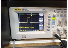
Noticed that the power on voltage to the IC was missing. Found two resistors near that rusted. Replaced the 1k and 330Ohms resistors, upon which the power came and the µController started working. The default LEDs were also found lit as mentioned in the service manual:
I decided to do all preventive maintenance works on all the boards as access to these boards was made very complicated and difficult by the designor. I separated the µController board, replaced all electrolytic capacitors, pressto-on micro switches and did dry solder patch up.
Did dry solder patch up on all other boards as well. Then took up the case of on/off switch lever fixing. Fist I fixed the broken leg and inserted component cut leads using soldering iron for ensuring proper hold in place. Then the two legs which go into the grooves under the front plate of the panel were steady and rugged. Then removed the front plate, removed button switch holding assembly one by one. Finally located the place where this lever had to be inserted and pushed it in into its groove. It was found held in place properly. Now Let us have look at the connected pictures, which might not be of much help as we need all these in front of us to do anything. But overall we might get an idea and that is all what we can expect:
Then fixed all boards back, tied the wires in a few places to hold together, and made it look as much better as possible.
Then played the set for a few hours before fixing the top cover and moving it out for delivery to the customer. Mission accomplished with aplomb which resulted in satisfaction getting added to the prestigious collections!
This article was prepared for you by Parasuraman Subramanian from India. He is 74 years old and has more than 30 years’ experience in handling antique equipment like Valve Radio, Amps, Reel Tape Recorders and currently studying latest tech-classes conducted by Kerala State Electronics Technicians’ Association. He has done graduation in BBA degree, private diploma in Radio Engineering and retired as MD of a USA company. Presently working as Consultant to Hospital and other institutions.
Please give a support by clicking on the social buttons below. Your feedback on the post is welcome. Please leave it in the comments.
P.S-If you enjoyed reading this, click here to subscribe to my blog (free subscription). That way, you’ll never miss a post. You can also forward this website link to your friends and colleagues-thanks!
You may check on his previous article on
Likes (1)Dislikes
 (0)
(0)
//
(tiêu đề viết lên đầu)
Revisit Of MARANTZ PM75 Amplifier With Different Problems
I request you all to see this link, in which I had reported about the first visit of this complicated, crudely designed amplifier with a hell of a lot of interconnecting wires.
I am including only the images relevant to the problem handled. Though I had told the customer that without dismantling the entire set, cleaning all boards, replacing all electrolytic capacitors and retouching every point in the boards, this set would not work without any trouble for a prolonged time, budget as well as time from my side and my aversion in handling such crude sets prevented to carry out such mass repair works. Result was that it returned with the complaint that only power on indicator was working and there was no other response to keys pressed. The first visit was in July, 2024 and the second visit was in December, 2024. I did a primary check of all the voltages and found these to be present. Next step was to check whether the µController was getting the voltages. I took print out of all the relevant pages required for trouble shooting. In order for me to access the µController which was fixed under the front panel, I had to, not only detach the front portion, but also disconnect dozens of wires, most of which were wire-wound connections!
Without detaching the wires, the control board could not be removed from the panel as these were fixed with screws from behind. To get the panel, we also need to remove other boards such as headphone socket, power indicator, speaker selector switch, bass/tone control board, record selector switch and volume control board, all of which were inter connected with short wires. How these people assembled the set itself was a mystery! I really struggled to take it out without causing any man made damages and if I had cursed the designers, I cannot be blamed for that! Let us look at some step-by-step images:
After removing the boards, I was shocked to see the crude modifications done by a previous technician who had worked on it, as reported by me last time and I promptly shared the images with the customer. Two ICs were missing in the volume control board and a relay was fixed at the bottom, function of which is known only to the guy who did it. The lever of the power on/off switch had broken and luckily it was found inside the front panel. The rest of the lever came off while I was taking the panel. I left that to deal with it later. Let us have a look at these modifications:
The volume control board itself had 9 connectors, which I removed after giving different markings for identification and also took snaps to avoid making mistakes. Then covered all the adjacent boards in bubble sheets and put rubber bands so as to prevent its accidental touch anywhere else. Then applied power to check the µController based on the circuit diagram.
Noticed that the power on voltage to the IC was missing. Found two resistors near that rusted. Replaced the 1k and 330Ohms resistors, upon which the power came and the µController started working. The default LEDs were also found lit as mentioned in the service manual:
I decided to do all preventive maintenance works on all the boards as access to these boards was made very complicated and difficult by the designor. I separated the µController board, replaced all electrolytic capacitors, pressto-on micro switches and did dry solder patch up.
Did dry solder patch up on all other boards as well. Then took up the case of on/off switch lever fixing. Fist I fixed the broken leg and inserted component cut leads using soldering iron for ensuring proper hold in place. Then the two legs which go into the grooves under the front plate of the panel were steady and rugged. Then removed the front plate, removed button switch holding assembly one by one. Finally located the place where this lever had to be inserted and pushed it in into its groove. It was found held in place properly. Now Let us have look at the connected pictures, which might not be of much help as we need all these in front of us to do anything. But overall we might get an idea and that is all what we can expect:
Then fixed all boards back, tied the wires in a few places to hold together, and made it look as much better as possible.
Then played the set for a few hours before fixing the top cover and moving it out for delivery to the customer. Mission accomplished with aplomb which resulted in satisfaction getting added to the prestigious collections!
This article was prepared for you by Parasuraman Subramanian from India. He is 74 years old and has more than 30 years’ experience in handling antique equipment like Valve Radio, Amps, Reel Tape Recorders and currently studying latest tech-classes conducted by Kerala State Electronics Technicians’ Association. He has done graduation in BBA degree, private diploma in Radio Engineering and retired as MD of a USA company. Presently working as Consultant to Hospital and other institutions.
Please give a support by clicking on the social buttons below. Your feedback on the post is welcome. Please leave it in the comments.
P.S-If you enjoyed reading this, click here to subscribe to my blog (free subscription). That way, you’ll never miss a post. You can also forward this website link to your friends and colleagues-thanks!
You may check on his previous article on
Likes(1)Dislikes(0)
//
[su_box title=”Liên hệ đặt mua sản phẩm tại bài viết tại Viễn Đông Mobile” style=”default” box_color=”#3be863″ title_color=”#FFFFFF” radius=”3″]
Viễn Đông Mobile là cửa hàng chuyên kinh doanh các sản phẩm điện tử phục vụ nhu cầu chơi game, bao gồm:
- Gaming phone: Điện thoại cấu hình mạnh, tối ưu cho việc chơi game.
- Máy tính bảng chuyên gaming: Màn hình lớn, hiệu năng cao, trải nghiệm game tốt hơn.
- Phụ kiện cao cấp: Tai nghe, bàn phím, chuột,… hỗ trợ game thủ.
Thông tin liên hệ:
- Địa chỉ: 211 đường 3/2, phường 11, quận 10, TP.HCM
- Điện thoại: 0777600020
- Email: contact@viendongmobile.com

Bản đồ chỉ đường
[su_gmap address=”211 đường 3/2 phường 11 quận 10 Tp hồ chí minh Việt Nam” responsive=”yes”] xin chào Xem chi tiết và đăng ký[featured_image]